Rail system guide
How to plan a pedestal rail system correctly
With a rail construction, terrace slabs do not rest only on individual pedestal heads but along parallel aluminium profiles. This can stiffen large formats and create a very level substructure, but it requires a carefully planned grid. Slab size, rail direction, perimeter support, profile joints and the selected manufacturer’s permitted spacing all matter. The calculator maps this geometry directly onto your floor plan.
The planning tool opens after free sign-up.
By the floorplanning.app editorial team
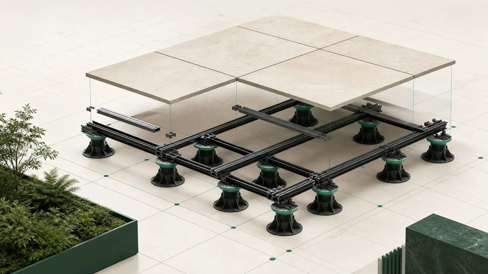
Rail, pedestal and slab form one system
The pedestals first support the aluminium profiles; the slab then rests with its edge or designated support zone on those profiles. Pedestals can therefore no longer be derived from slab corners. They belong directly under every rail: at each section start and end and at permitted intervals in between. In the plan, rails are brown, perimeter rails darker, and support points are coloured by corner, edge and interior.

What matters in practice
50 cm below the rail, no more than 60 cm between rails
Manufacturer limits are not identical: DURAL specifies a maximum of 50 cm between pedestals for FLEXIBAL. Profilitec specifies 50 or 60 cm for UPTEC depending on joist length and also limits parallel rail spacing to 60 cm. Because the calculator does not assume a brand, it uses conservative limits: supports no more than 50 cm apart and rail spacing no more than 60 cm. The data sheet of the system actually ordered and the slab’s load capacity still remain binding.
Edges and cutouts need dedicated support
A perimeter rail does not belong only at the top and bottom of a bounding rectangle. The inner corner of an L-shape, the edge of a cutout or the end of a wall also creates a real surface edge. The calculator adds a rail line there and marks only the portion actually running along the perimeter. If a cutout separates a rail, each new section gets its own end support. Door openings remain passages and a rail can continue through them.
Shared axes instead of drifting support points
If supports are distributed evenly on each rail independently, sections of different length create staggered rows. The maximum distance may still be respected, but the plan looks irregular and installation becomes unnecessarily difficult. The calculator therefore uses shared 50 cm axes across the construction. Only an edge, cutout or section end adds an extra point. Adjacent support rows remain aligned and the plan is easier to transfer to site.
Quantities calculated by the tool
Every real rail run produces traceable material quantities rather than a flat value per square metre.
- Total rail length and perimeter-rail share
- Profile pieces from the selected standard length
- Longitudinal connectors for profile joints
- Pedestals directly below the rails
- Reduced pedestal height due to rail height
Plan a rail system in 4 steps
1. Draw area and cutouts
Capture the outer contour, L-shapes, walls, doors and every area without flooring.
2. Set slab and joint
Size, thickness, joint width and laying direction determine the supporting grid.
3. Enable the rail system
Check the suggested spacing and direction; the brand-neutral calculator does not allow more than 60 cm.
4. Review quantities and warnings
Use rail metres, pieces, connectors and supports only after checking the system and slab data sheets.
Examples from the tool
This is what it looks like planned out
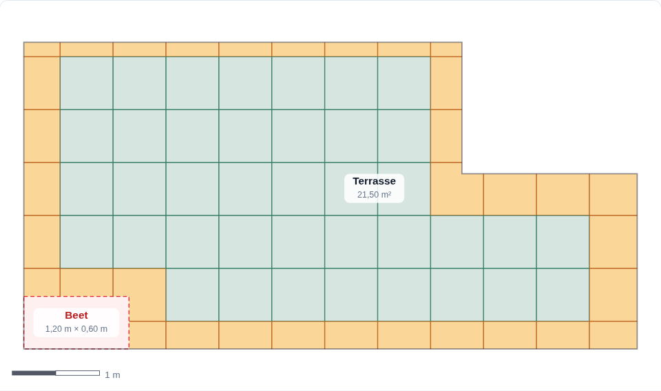
The numbers above do not come from a spreadsheet but from a real layout. You can open these example projects directly – floor plan, laying plan and material list, exactly as the tool outputs them.
Opens the read-only client view of a share – the same one you create for your own projects with Premium.
Common rail-system questions
How far apart may pedestals below rails be?
It depends on the system. DURAL FLEXIBAL specifies a maximum of 50 cm; Profilitec UPTEC specifies 50 or 60 cm depending on joist length. The calculator uses a brand-neutral maximum of 50 cm.
Must every perimeter have a rail directly at the edge?
Every relevant slab edge needs the support specified by the system. The calculator therefore places a perimeter rail along axis-parallel outer and inner edges and an end support at perpendicular edges.
How are long rail runs connected?
For lengths over 2.40 m, Profilitec describes either a 5 mm gap between profiles or the designated SUPAJG connector. Other systems use their own connectors. In the calculator you enter the actual standard length, which determines piece and connector counts.
Can every slab format be laid on rails?
No. The slab must be approved for the intended line support, span, load and outdoor application. Size and thickness alone do not replace approval by the slab and system manufacturers.
Related calculators & guides
- Plan rails in the pedestal calculatorUse a pedestal paver calculator for terrace slabs: plan supports at corners, edges, and in the field, then get a reliable material quantity.
- Pedestals or a rail system?Compare pedestal pavers and rail systems for terrace slabs: support, spacing, edge details, and the manufacturer limits that decide.
- Gravel, pedestals or mortar?Gravel bed, pedestals or drainage mortar: which installation fits your terrace – plus planning slope, joint width and edging correctly.
Plan rails directly on your floor plan
Enter the area and slab size, enable the rail system and automatically derive supports, profiles and connectors.
The planning tool opens after free sign-up.