Pedestal planning guide
Four corners do not mean four pedestals per slab.
Neighbouring slabs share their supports within a regular field. The count changes at edges, corners, cutouts and under large formats. Here is how to turn a slab grid into a realistic bill of materials without ignoring the slab manufacturer’s safety requirements.
The planning tool opens after free sign-up.
By the floorplanning.app editorial team
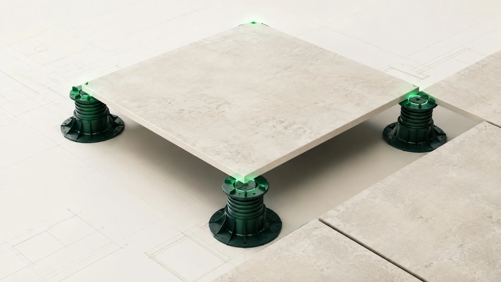
The short answer for 60 × 60 cm slabs
For a regular 60 × 60 cm slab approved by its manufacturer for corner support, place a pedestal at every grid intersection. Four slabs meet at an interior point and share that support. One isolated slab needs four supports, but a field of many slabs needs far fewer than four pedestals per slab.

Pedestals = (slabs per row + 1) × (rows of slabs + 1)
Example: A 5 × 4 field contains 20 slabs but only 6 × 5 = 30 unique grid points.
Only valid for a complete rectangle using corner supports. Edge details, cut pieces, large formats and manufacturer instructions may add supports.
What matters in practice

Treat field, edge and corner positions separately
An interior pedestal can carry four slab corners, an edge pedestal usually two and a corner pedestal only one. That is why “number of slabs × four” fails. Draw every joint line first, then count unique intersections rather than counting every slab corner separately.

Irregular areas need an actual layout
An L-shape, planting bed or column breaks the regular grid. New edge points appear, some supports must be divided or moved and narrow cut pieces may require extra support. Row × column is no longer enough; the actual remaining geometry matters.

Large formats: extra supports or a rail system
Large and elongated slabs cannot automatically be supported only at four corners. Depending on size, thickness, material and use, the manufacturer may require centre supports, extra pedestals along long edges, backing reinforcement or a continuous substructure. That instruction overrides any online rule of thumb.
Check these locations individually
- Outside and inside terrace corners
- Wall junctions and exposed perimeter edges
- Cutouts for drains, posts and planting beds
- Narrow or L-shaped cut slabs
- Slab joints at steps and thresholds
- Large formats requiring centre supports
- Transition between point and rail support
- Areas with higher loads or fall risk
Example support layouts for stone slabs
These examples come from Eurotec’s terrace catalogue and show why slab size changes support requirements. They are not approval for a different slab product.
| Slab size | Example support layout |
|---|---|
| 60 × 60 cm | 4 corner supports |
| 80 × 80 cm | 4 corners + centre |
| 90 × 90 cm | Corners + edge midpoints + centre |
| 120 × 40 cm | Corners + midpoint of long edges |
| 120 × 60 cm | Corners + long edges + centre |
What you actually need for the parts list
The slab count alone is not enough. Size, grid, perimeter and approved support positions together produce a reliable quantity.
- Exact floor plan including every cutout
- Slab size, thickness and exact product reference
- Selected joint grid and laying direction
- Support layout approved by the slab manufacturer
- Perimeter restraint, wall clearance and exposed edges
- Lowest and highest points of the load-bearing substrate
- Desired finished level and drainage direction
- System parts such as spacers, pads, clips and connectors
How to calculate the pedestal count
1. Read the slab approval
First confirm that the slab is approved for loose raised installation and which support layout its manufacturer requires.
2. Draw the load-bearing area
Include the perimeter, drains, posts, planting beds, steps and every area where a pedestal cannot stand.
3. Set the slab grid
Set slab size, joint, direction and starting offset. Only now are the actual slab corners known.
4. Count unique grid points
Count each physical point once, regardless of whether one, two or four slabs meet there.
5. Add extra supports
Add centre and edge supports required by the slab approval. Review every cut slab individually.
6. Plan perimeter restraint
Decide how exposed edges are restrained against lateral movement and how wall junctions avoid damaging waterproofing.
7. Assign height ranges
Substrate level, desired finished level and slab thickness determine pedestal height. Verify that every support stays within its adjustment range.
8. Order a system-specific reserve
Allow a few spare pedestals and small parts, but do not use reserve to replace a geometry check. Count perimeter accessories separately.
Examples from the tool
This is what it looks like planned out
The numbers above do not come from a spreadsheet but from a real layout. You can open these example projects directly – floor plan, laying plan and material list, exactly as the tool outputs them.

Opens the read-only client view of a share – the same one you create for your own projects with Premium.
Common questions about pedestals per slab
Does every slab need four separate pedestals?
No. Several slabs share a pedestal within the field. Only an isolated slab needs four separate supports. Count the unique support points of the complete grid.
How many pedestals do I need for 20 slabs?
A complete 5 × 4 grid using corner supports has 30 points. A different arrangement, cutouts or a format requiring extra supports changes the count.
When does a slab need a centre support?
The specific slab manufacturer’s approval decides. Size, thickness, material, load and build-up height interact. Example tables and rules of thumb cannot replace that instruction.
Can a pedestal base be cut at a wall?
Some systems provide defined break or cut zones; others use dedicated perimeter supports. Never improvise: follow the system manual and protect the waterproofing.
Does floorplanning.app calculate structural safety?
No. The tool plans geometry, quantities and approximate heights. Load capacity, wind load, fall safety and approval of the complete system require professional assessment.
Related terrace guides
- Open the pedestal calculatorUse a pedestal paver calculator for terrace slabs: plan supports at corners, edges, and in the field, then get a reliable material quantity.
- Plan a pedestal rail systemPlan aluminium rails on pedestals correctly: calculate rail and support spacing, perimeter support, cutouts, profile pieces and connectors.
- Compare point supports and railsCompare pedestal pavers and rail systems for terrace slabs: support, spacing, edge details, and the manufacturer limits that decide.
- Calculate terrace slab quantitiesCalculate how many terrace slabs you need: count edge and corner cuts, include waste, and estimate the right quantity before ordering.
Sources & technical references
Technical values can vary by product and build-up. When in doubt, the current installation instructions for the actual system always take precedence.
- Terrace catalogue: recommended support for stone coverings
Eurotec GmbH
Manufacturer catalogue with support examples from 60 × 60 to 120 × 120 cm and an explicit reminder to follow the slab manufacturer’s instructions.
- Installation manual for 20 mm porcelain stoneware
Mirage Granito Ceramico
Primary source on raised installation, positioning supports by slab size, substrate fall and the limits of example build-ups.
- Technical safety information for raised paving
Mirage Granito Ceramico
Warnings covering impact fracture, backing reinforcement, intended use, wind load and local requirements.
Calculate pedestals from your slab grid
Draw the terrace, set the slab grid and turn every unique support point, including edges and cutouts, into a parts list.
The planning tool opens after free sign-up.